This tutorial was developed in collaboration with Pierre Emery.
The main goal of this project is to obtain a perfect finish for the upper surface after bagging. This means that the openings, e.g., the spar box and the wire opening, must be cut from the lower surface. Since the spars are perpendicular to the tip, they have to be cut in a separated pass. This also means that the profile has to be inverted so that the lower surface is now on top (and becomes the upper surface).
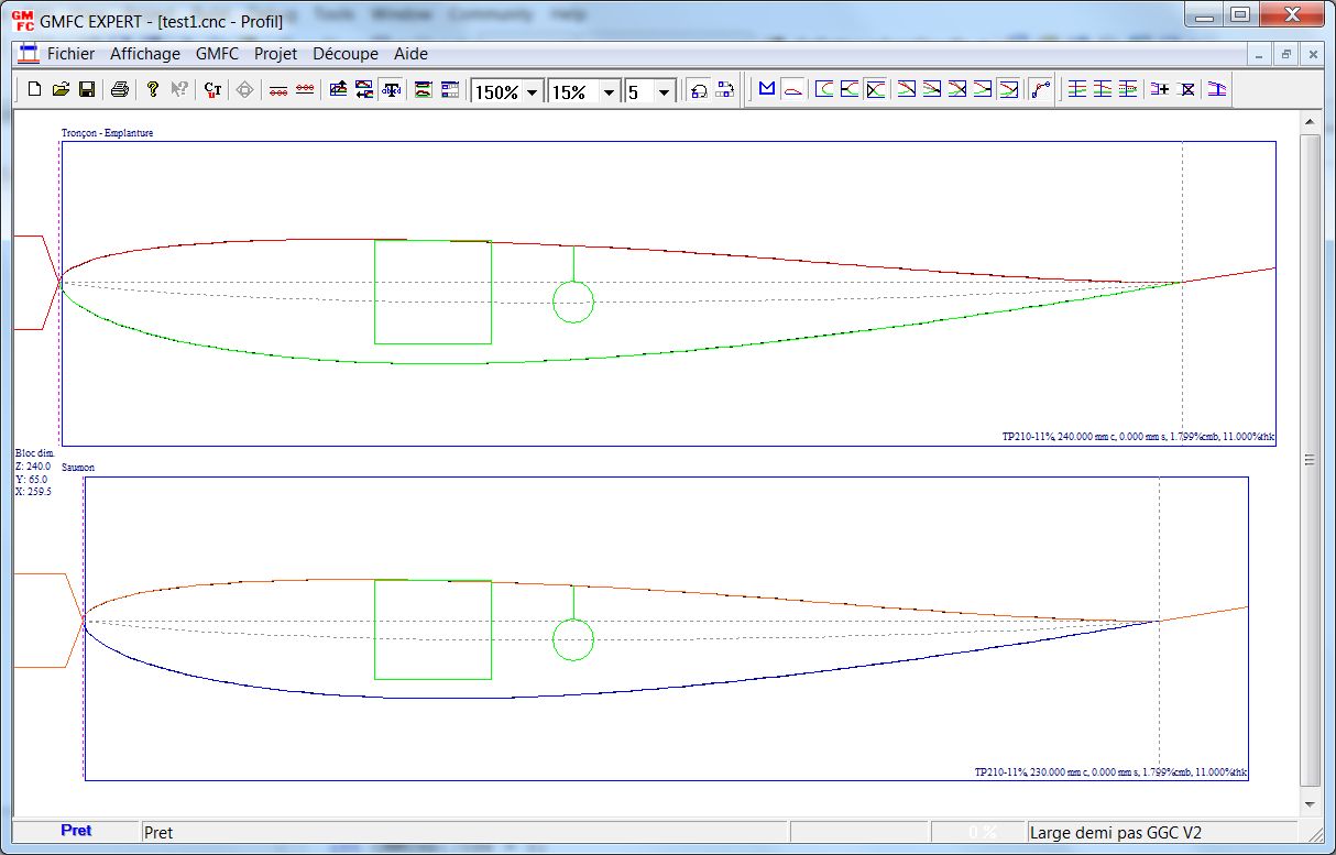
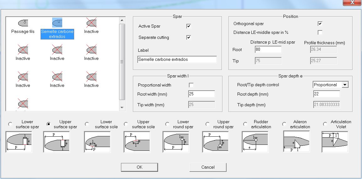
Here is the GMFC Expert project:
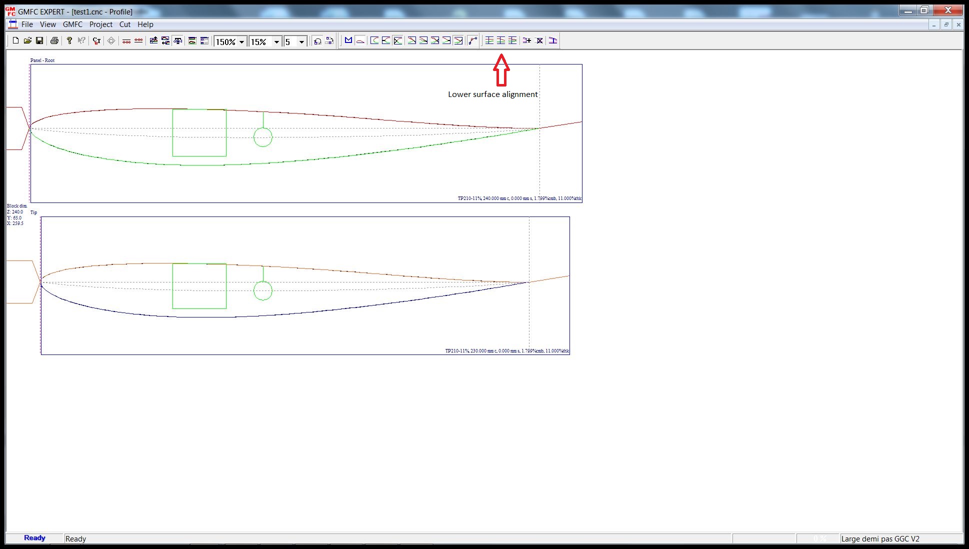
Both sides, root and tip, are vertically aligned using the lower surface (in fact the upper surface) as reference. Additionally, X cut at the leading edge should be used so that the upper bed can be removed after cutting the upper surface.
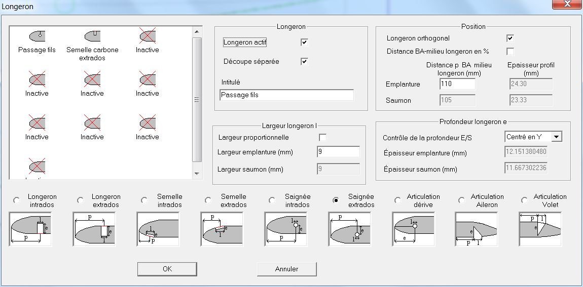
The hole for the servo wires is made using a perpendicular upper round spar, that is vertically positioned at the middle of the profile.
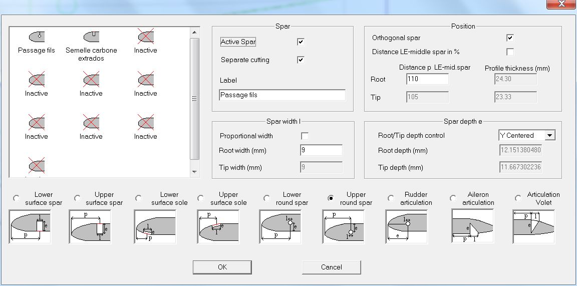
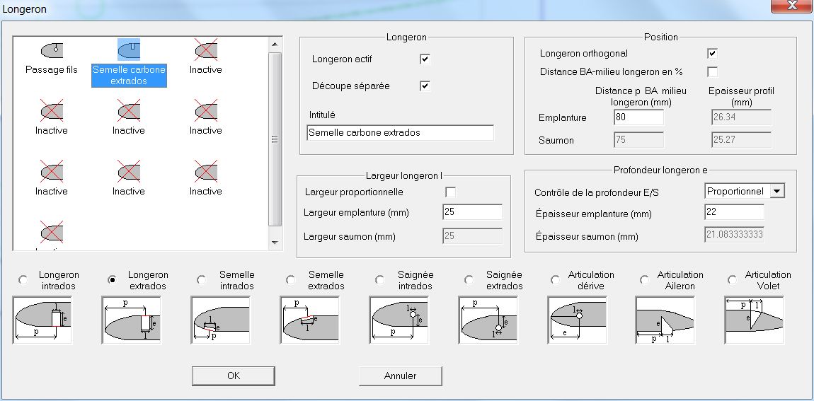
The spar box is made using a perpendicular upper spar. The spar depth is adjusted so that there remains a layer of foam of few millimeters. This foam layer will be removed after bagging the profile upper surface with fiberglass. This makes possible to realize a carbon sole against the glass skin and later to place the spar box while ensuring no deformation of the skin.
Let’s start cutting the project:
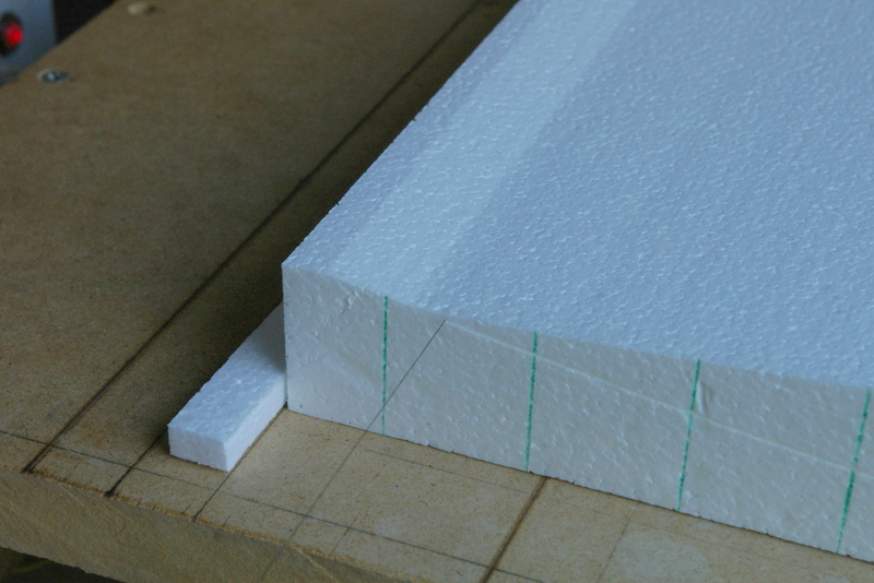
Since the foam bloc will be touched between the cutting phases, it’s likely that it will move. To ensure a correct positioning at all times, I place two rulers made from foam on the table using double side tape. The foam bloc will be placed against the rulers.
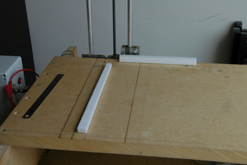
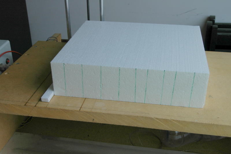
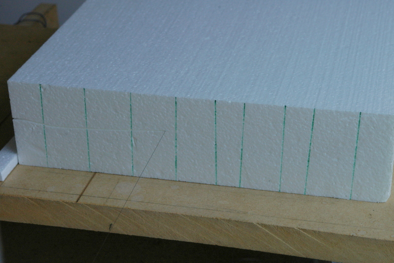
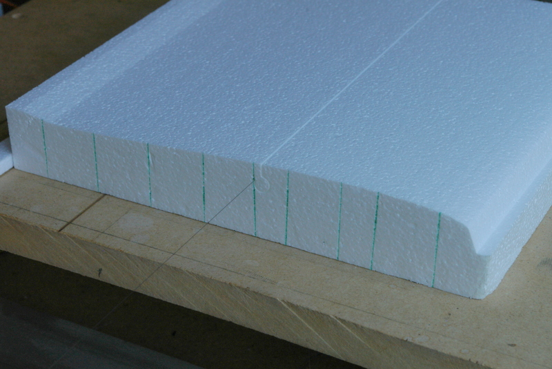
Note the vertical lines traced with a pen on the foam side. This will helps later positioning of the wing panel in the beds.
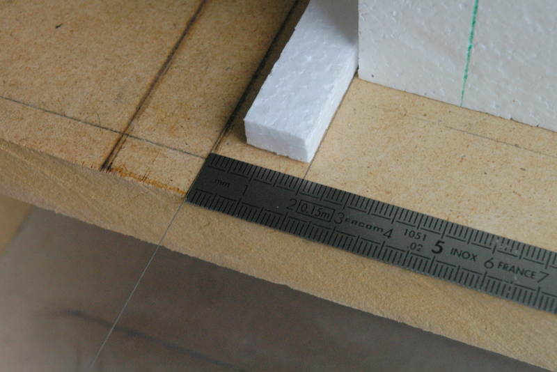
The initial step is to come up with a rectangular block that is about 10mm longer than the final block. It will be shaped to the final dimensions during the last phase. For now, the block sits against the ruler 20mm away from the 0 position of the wire.
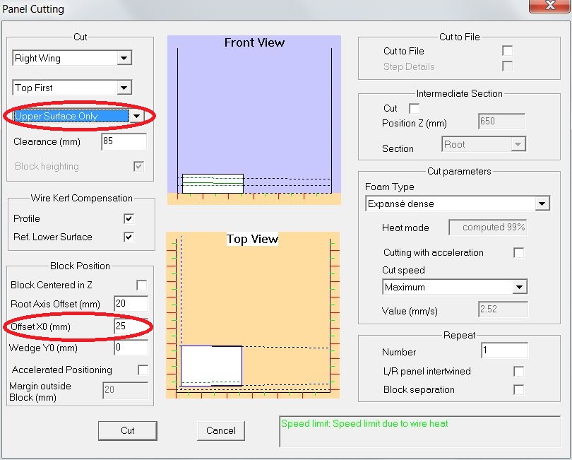
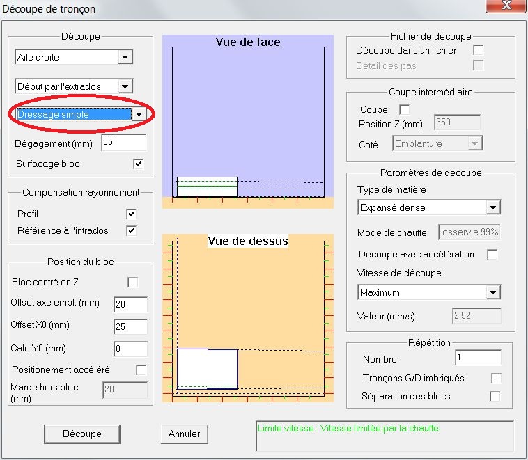
Now run the « cut panel » with the option « Upper surface only ». Note that X offset is set to 25mm, while the block sits at 20mm. This trick allows the usage of a rectangular block which simplifies positioning while the final block is shaped with taper.
Few pictures taken while cutting the upper surface:
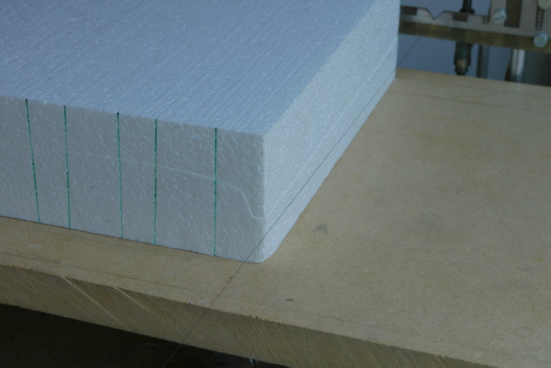
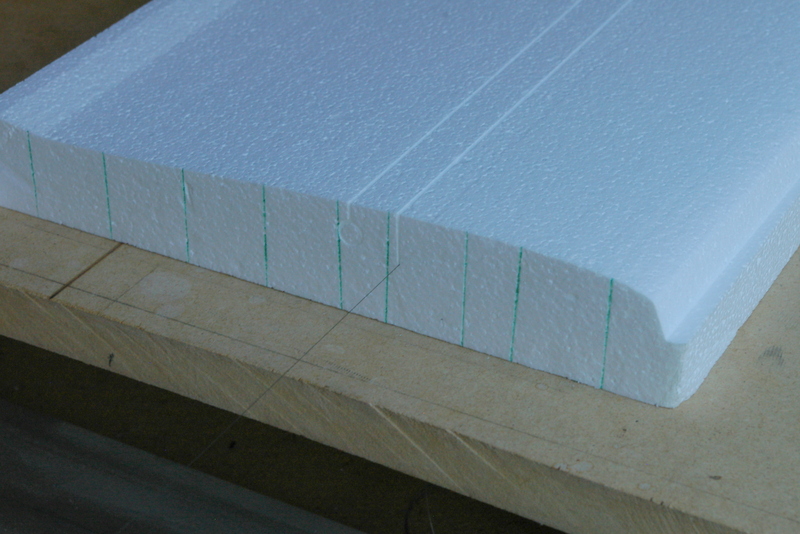
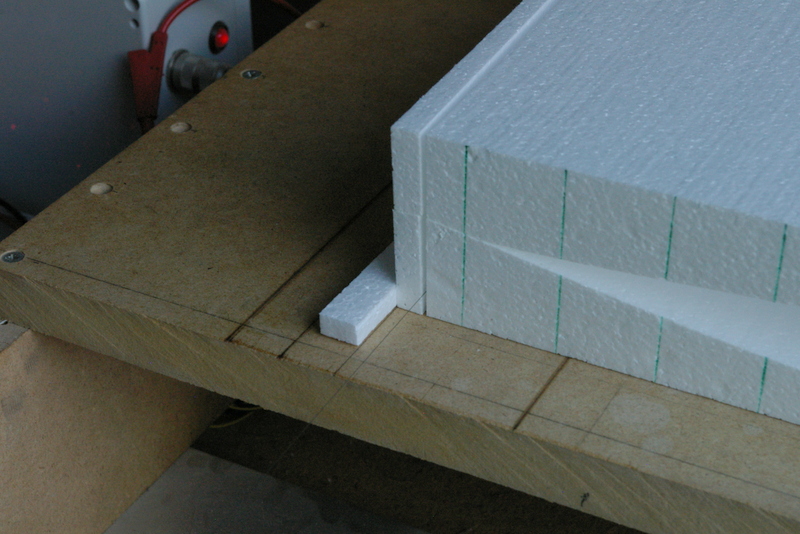
After cutting the upper surface, the wire stops outside the foam block. Now the upper bed should be removed. If the block moves, just put it back against the rulers.
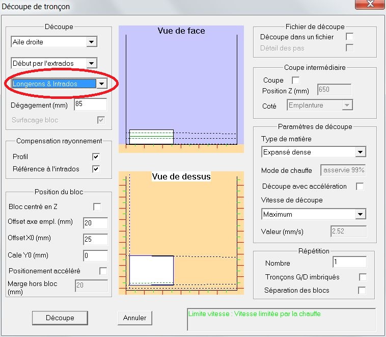
Now run the « cut panel » again and select the option « Spar & Lower surface ».
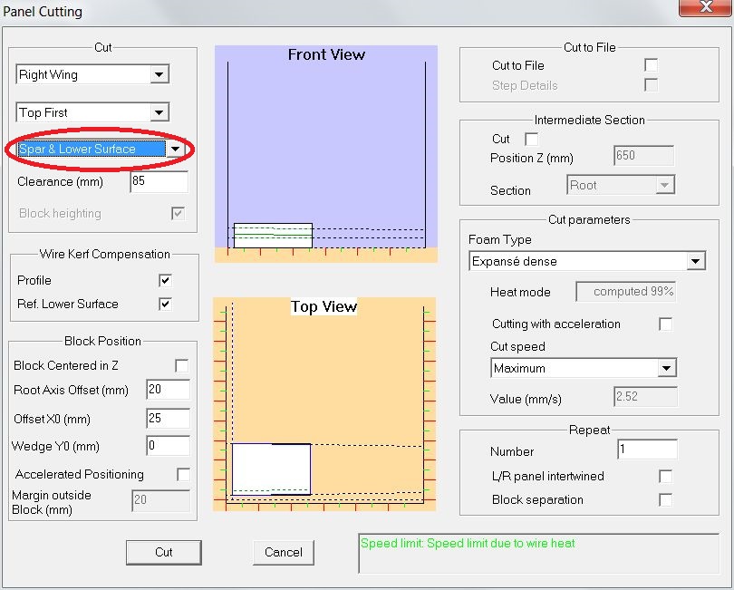
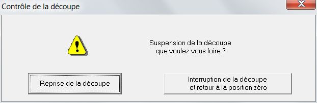
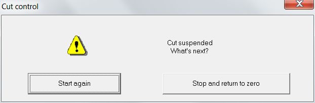
Note that GMFC Expert pauses after cutting the spars. You have to press on the button « Start again ».
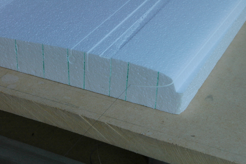
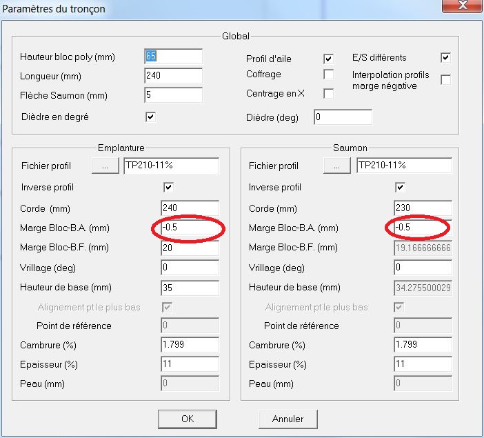
Now we have to shape the block to the final dimensions using the « cut panel » dialog again and the « Trimming only » option. I have defined a negative margin at the leading edge that is within 0.5mm the panel size, so the mylar will be adjusted against the LE during bagging.
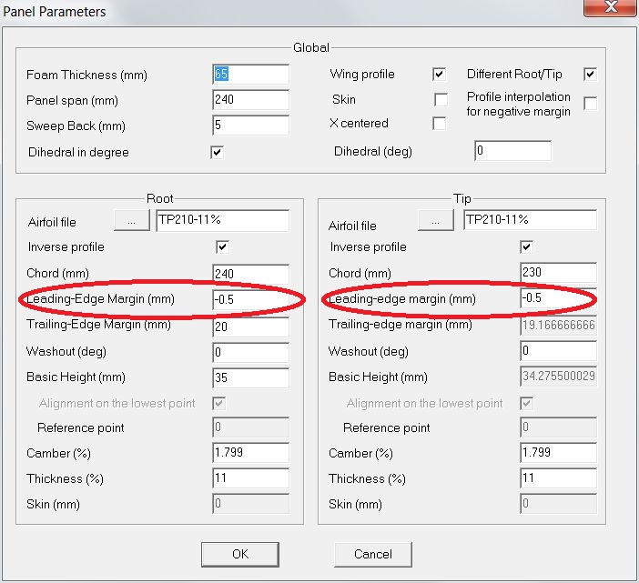
The negative margin implies that that the wing panel must be removed during shaping. Thanks to the X cut at LE, both beds sit against each other.
Note that the upper bed will fall down after the LE part is cut. Therefore, you must halt cutting while the wire sits down on the table and remove the top bed before the up phase.
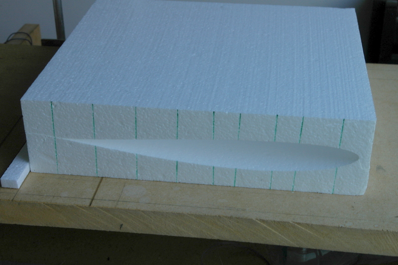
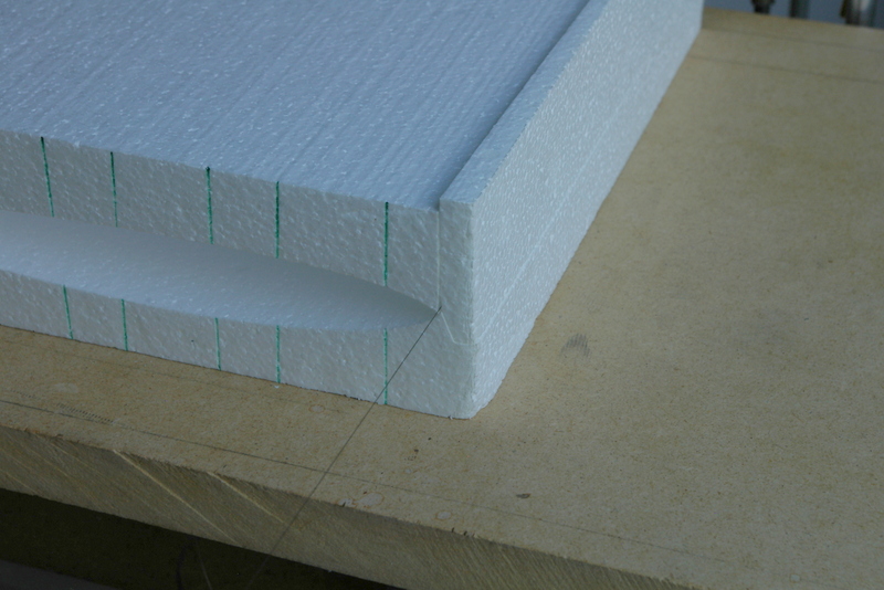
Here is the result after shaping:
When making a wing from several panels, it is necessary that the final foam blocks have the exact same heights. This can be done by making a final horizontal cut with the wing within the beds. This can be done either with the « foam cut dialog » or using the « Block heightening » option together with « Trimming only ».
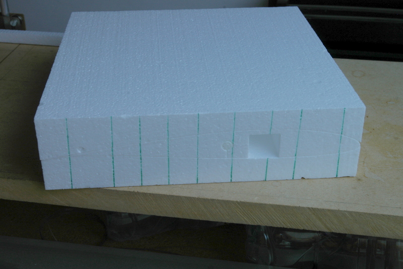
Finally, for vaccum bagging the upper surface, the main spar hole should be filed. The remaining of the cut spar can’t be used since it is too small due to kerf. Another one should be cut with correct dimensions…. stay tuned, there will be a next lesson…