Fusion 360 is a great CAD program, and quite easy to learn. For now, it is also free for personal usage. I have already used it to design few models.
Here is a tutorial that explains how to design a “simple” shape using Fusion and then exporting it into a GMFC EXPERT (and PRO) project.
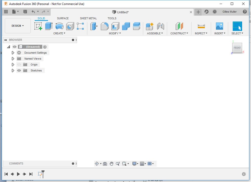
First, you need to start Fusion, and create a new design (File/New Design).
Using the view cube in the right, select the front view.
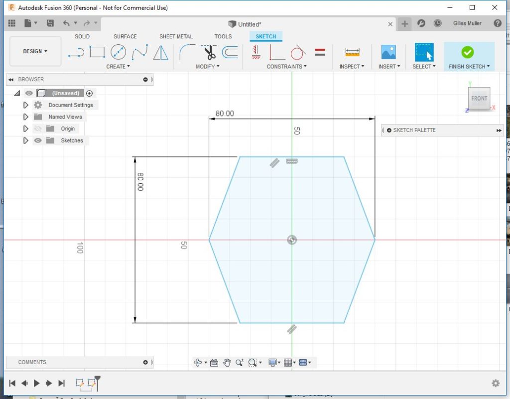
Then, create a sketch (Create/Create Sketch). Select the (front) plane to define the sketch on the front.

Now draw a hexagon using Lines. Then finish the sketch.
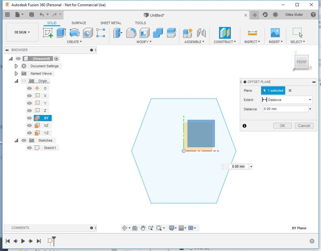
Now, we are going to create the second face. First, we need to create a second plane parallel to the first one. Use Construct/offset plane for this. Select the front plane which is the XY plane in the Origin section in the browser, and enter the distance between the two faces (here 60mm).
There is a new plane in the construction section. Right click on the plane and select “Create Sketch”.
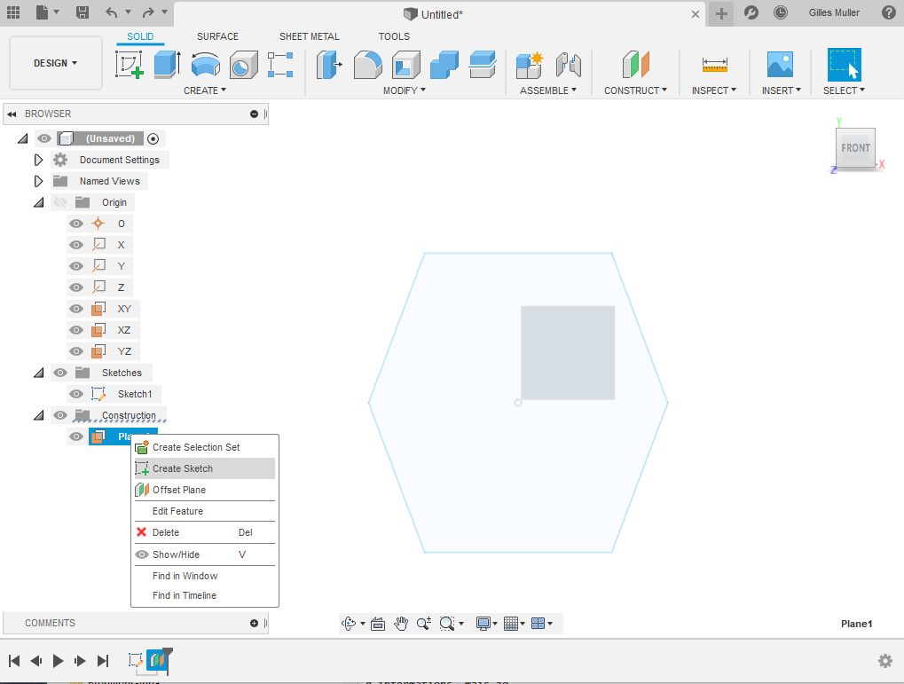
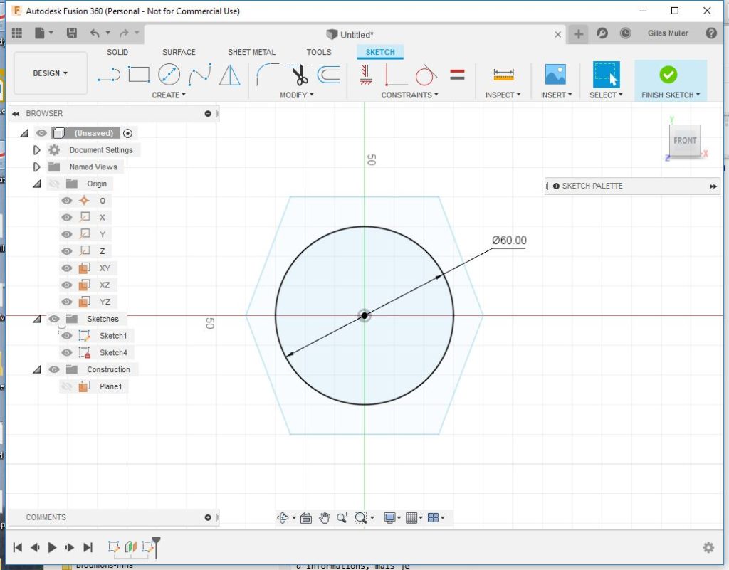
Draw a circle on this face, and center it with respect to the hexagon.
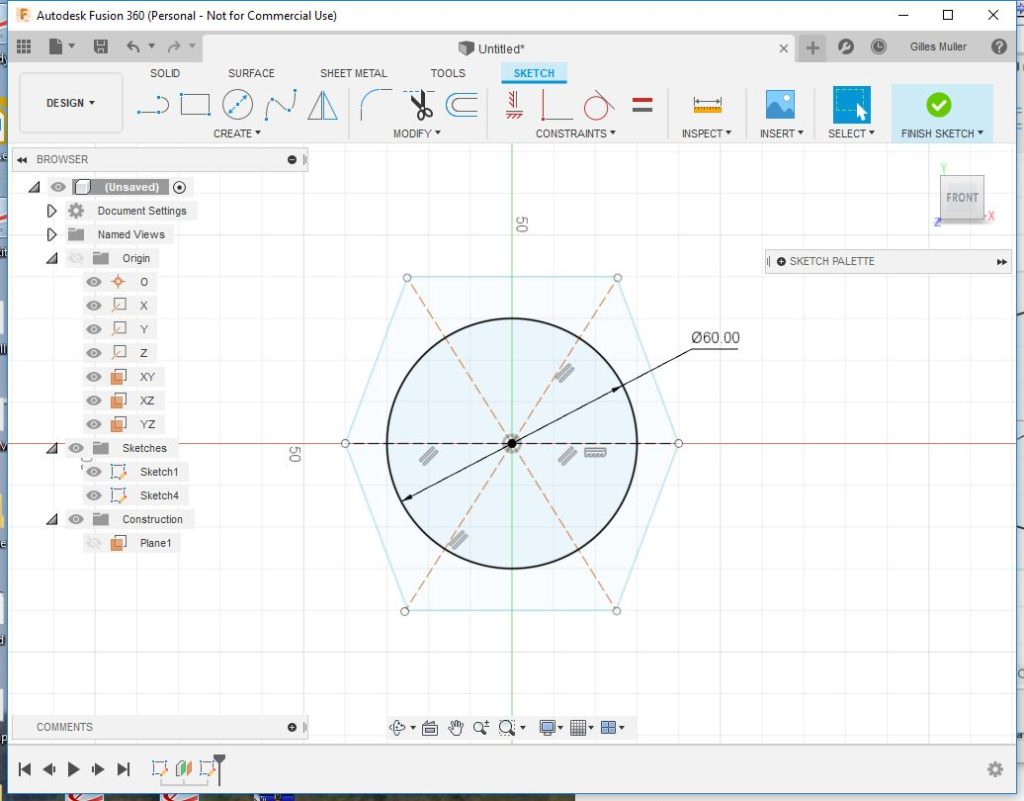
Now we need to split the circle so that we can synchronize both faces. Here we want to divide it in 6 parts corresponding to each side of the hexagon. For this, let’s draw lines from between each hexagon opposite points. Change the type of the lines to “Construction Lines”.
The next step is to break the circle at the intersection of the construction lines. Use the break tool in the “Modify” menu.
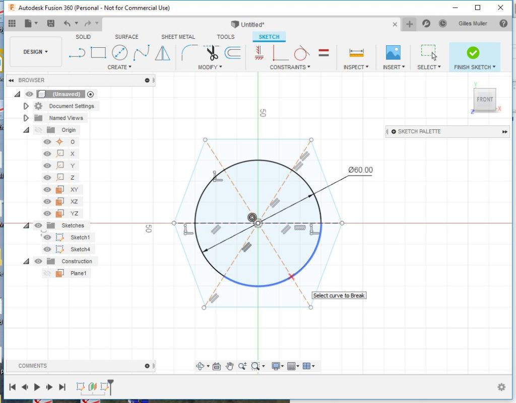
Cut also the construction lines outside the circle, using again the break tool. Then finish the sketch.
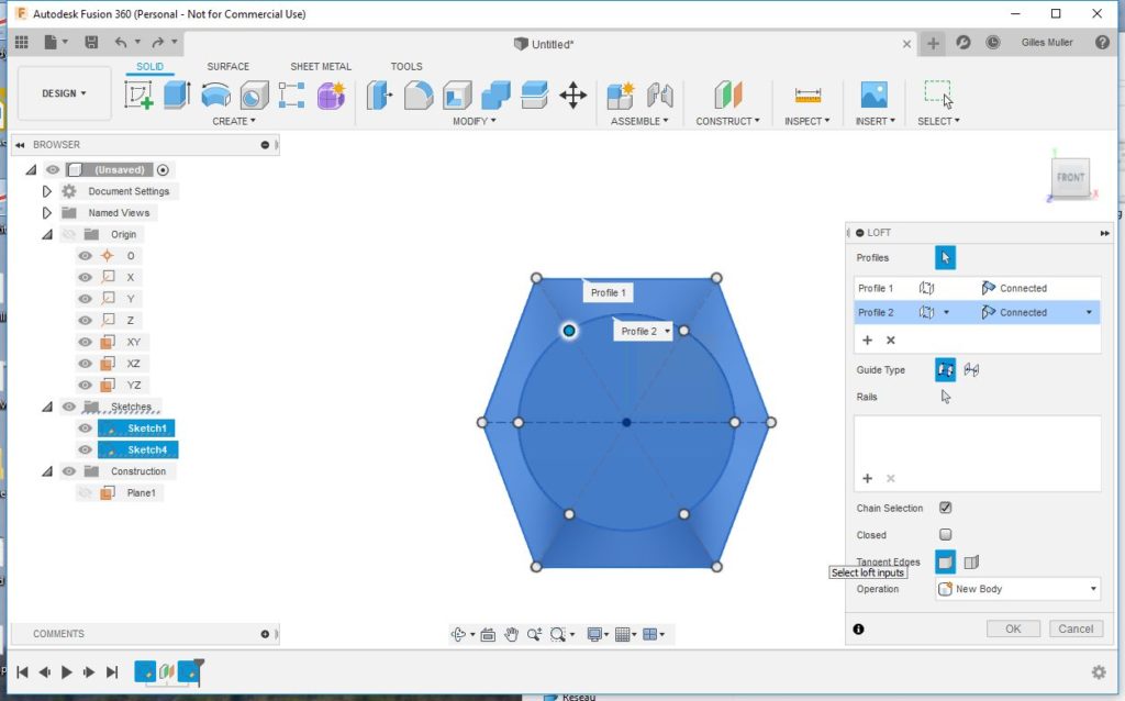
Now, we need to construct the 3D view of the object, so as to check the final result. Select the “Loft” tool in the create menu, then the two profiles.
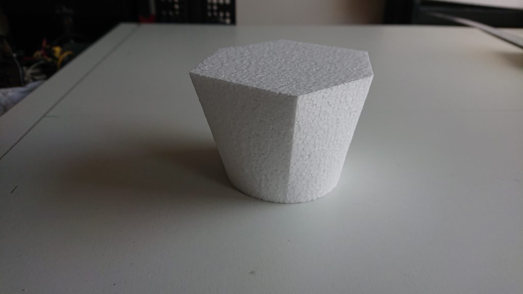
Here is the result.
Note that we could have split the circle in other ways. The construction lines are there only to ensure that all part are symmetric. What matters is that in the end there are the same number of segments in each profile.
Now we need to create a GMFC project from this shape. The solution relies on exporting both sketches into DXF files. Fusion does that, but it also exports construction lines which would require editing the DXF using a CAD program. My solution is to create a script for fusion that does the exportation while removing the construction lines.
First download the script. It is available here: http://gmfcsoft.fr/download/utility/ExportDXFSelection.zip
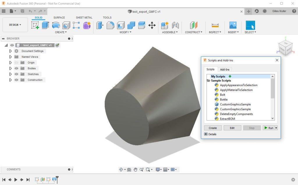
Uncompress the zip file in a directory. You need to install the script within Fusion. This should be done only once. Call the script menu using the “S” command. Then click on the green cross and select the installation directory. “ExportDXFSelection” should be now present under “My Scripts”.
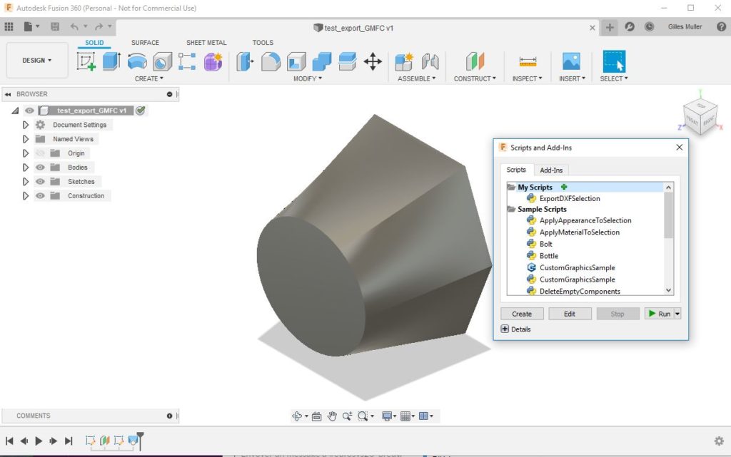
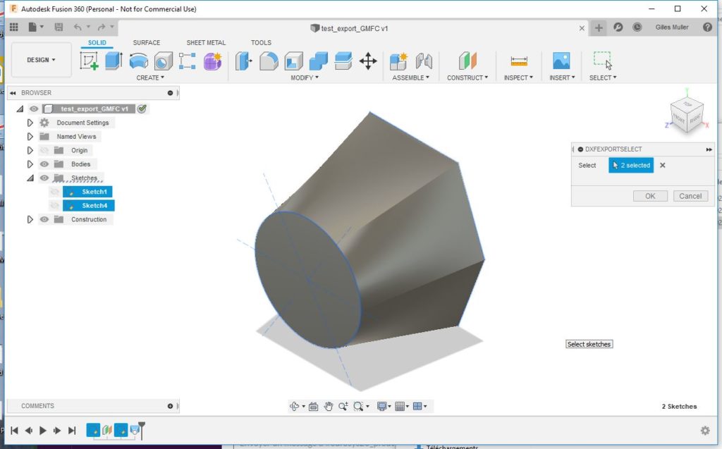
Select “ExportDXFSelection”, and click on “Run” to launch the script. A windows is displayed with the number of sketches selected.
Select the sketches you want to export, then click on “OK”. A new pop-up window appears for selecting a directory where the DXF are saved. There is a file for each sketch. The name is constructed by concatenating the design name and the sketch name.
Then for each sketch, the script displays the bounding box, i.e., the limits of the sketch.
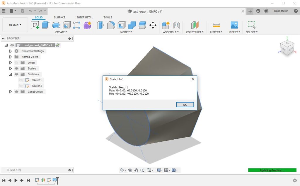
Finally, the script displays the delta in X and Y. This information is critical for correctly positioning both profiles when creating the GMFC project.

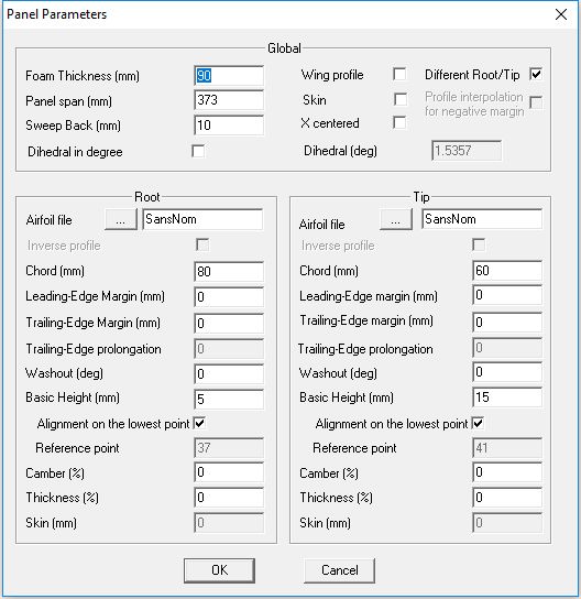
Now, we can create the GMFC project. Start GMFC, open the panel parameter. Select “Different root/tip”.
Enter the DeltaX value in the “Sweep back” field. Add the DeltaY value to the root “Basic Height” and enter it in the tip “Basic Height”. Enter the distance between the plans into “Panel span”.
Import both profiles using “File/import DXF”. For more details, follow the tutorial at https://gmfcsoft.fr/blog/?p=879.
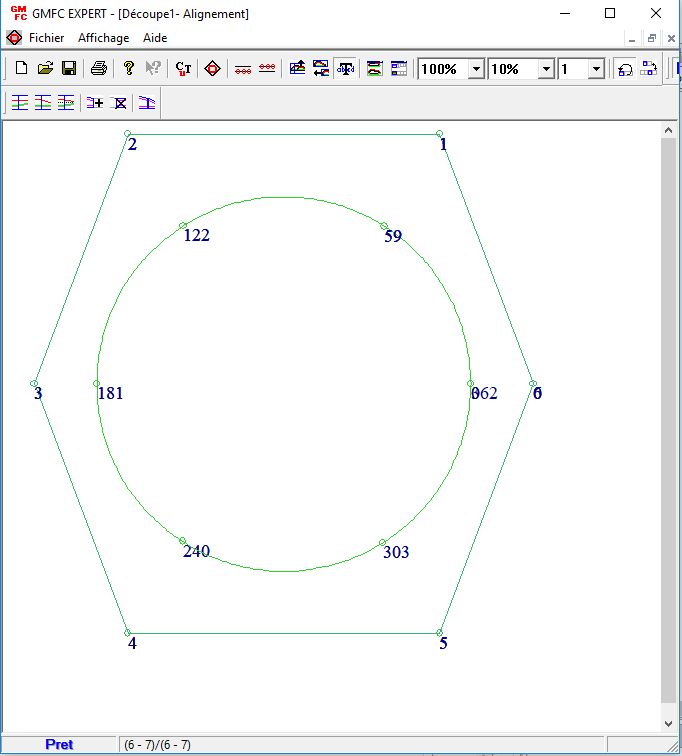
Enter the alignment mode. We need now to assign the same number of cutting points to each corresponding segment at root and tip.
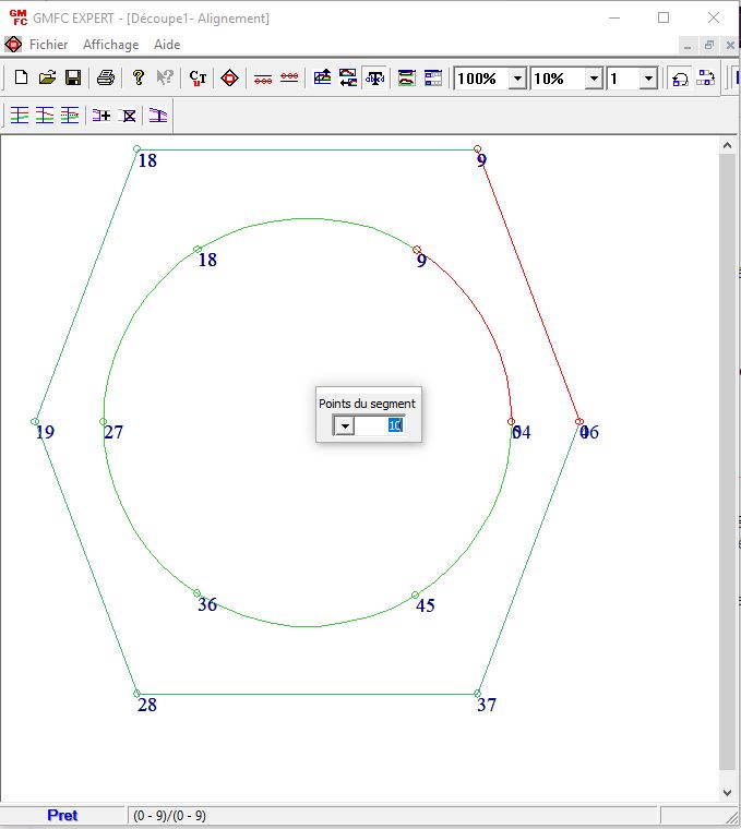
Double-click on a segment and set the number of points.
Voila, you are nearly done for the design part… now you have to cut the shape.
Note that this project induces a lot of sweep back in X and Y… I used a 100mm wedge for cutting the shape. Fortunately, my Y axes are large. Here is a video of the cutting…
This tutorial is for GMFC EXPERT. If you are using GMFC PRO, you need to transform the DXF files using a CAD tool. Split each segment into the desired number of lines, then finally merge them into a polyline.