TB6600 drivers are interesting because they can work up to 40V and 4A. Therefore, they can drive a large variety of bipolar stepper motors. These drivers are also affordable with a price below 10 euros on ebay or aliexpress.
TB6600 drivers are available under several packaging with different maximal current and voltage. However, connections are mostly identical.
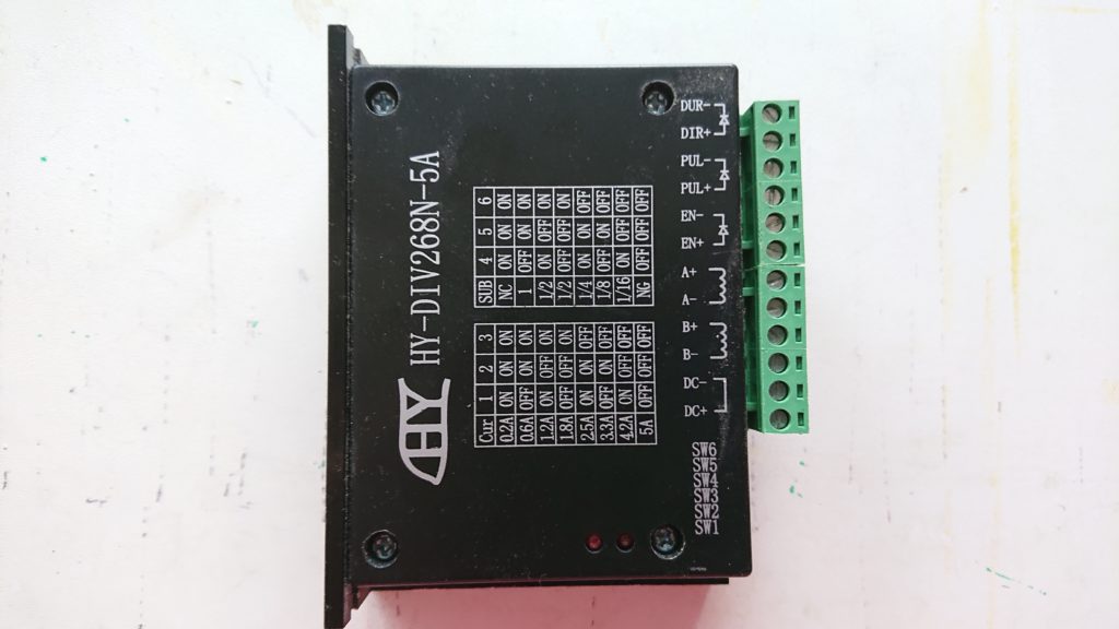
On the motor side, there are :
- VCC (DC+), GND (DC-) that must be connected to the motor power supply.
- A+,A- and B+,B- the four motor signals.
On the GGC side, there are:
- PUL+, PUL- that are the step control signal.
- DIR+, DIR- that control the direction of the move.
- ENA+, ENA- that control powering of the motor. This signal is optional and avoids heating the motor when not used.
The PUL+, DIR+ et ENA+ should be connected to +5V on the GGC. The pin 20 on port J4 can be used for this purpose as shown on the following picture.
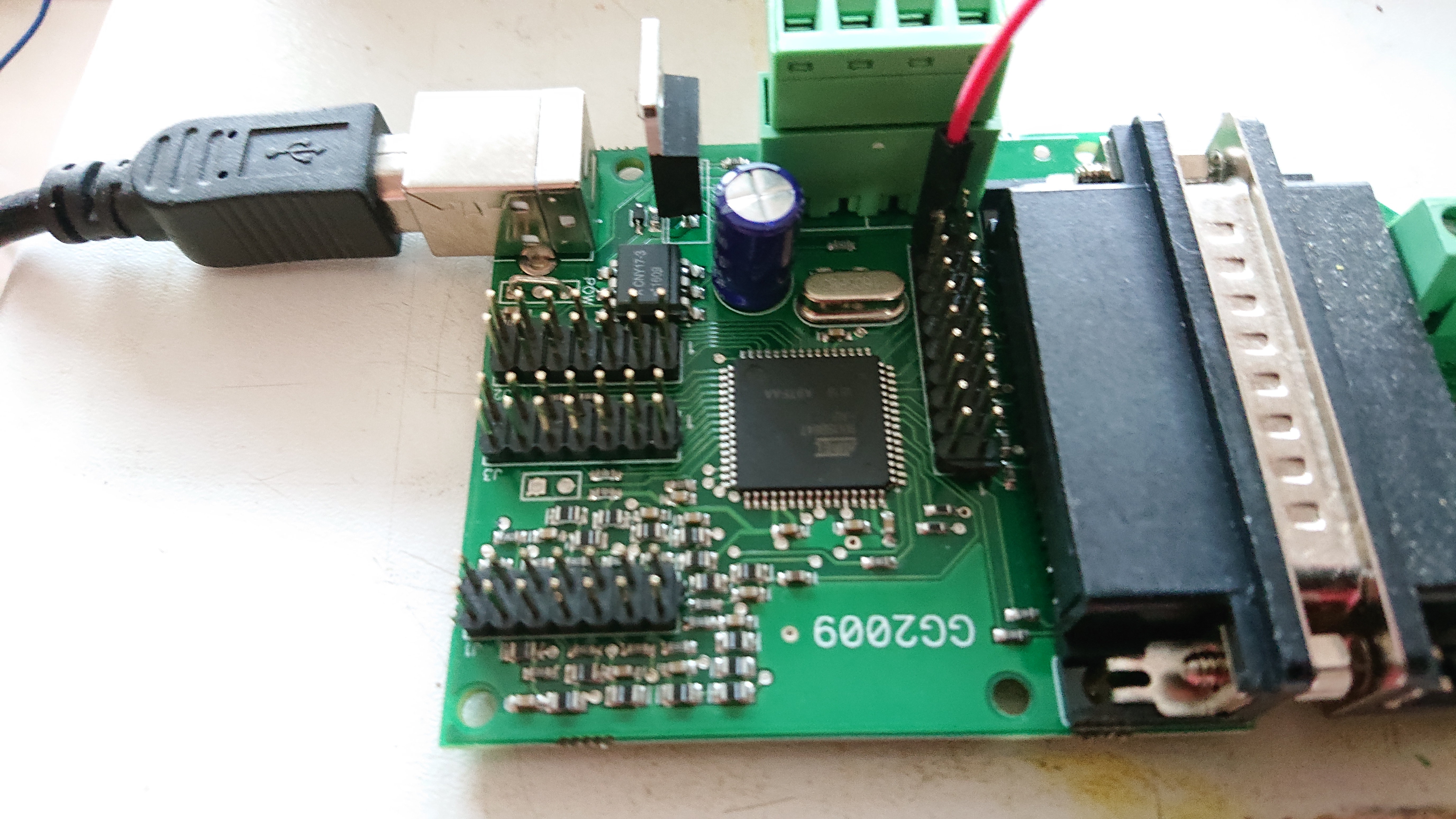
ENA- should be connected to the DB25 parallel port, either to pin 1 or to pin 17. PUL- should be connected to pin 2, DIR- should be connected to pin 3. Other motor drivers should be connected to pin 4 to 9. This is only an example since the configuration of STEP and DIR signals is fully configurable within the ggc_utility.
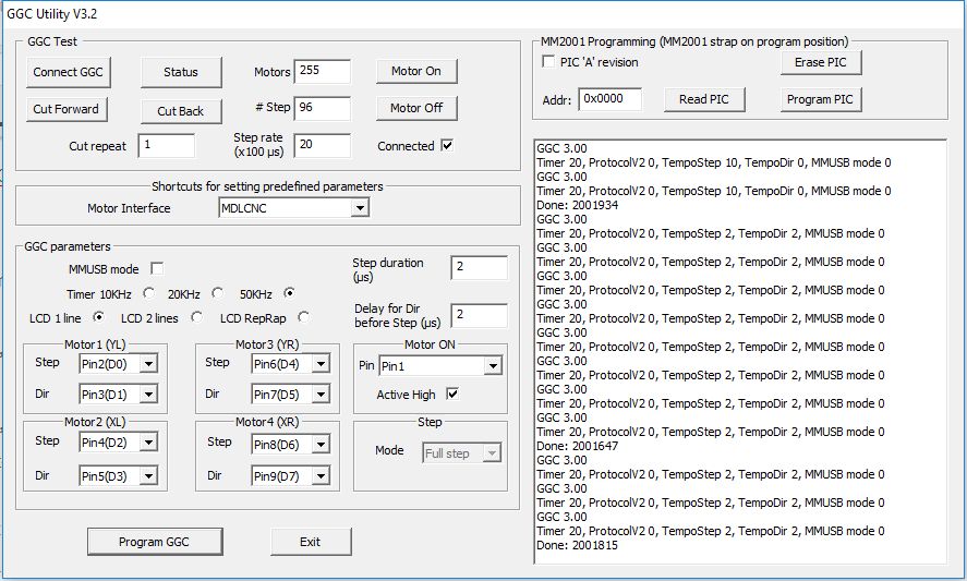
Using the ggc_utitity the timer should be set to 50Khz, the duration of the STEP signal and the delay for Dir before Step should be set to 2 us. Here, Motor ON is on pin 1, and should be Active High.
Several DB 25 pins are also available on J4:
- DB.17 (Motor Enable) -> J4.2
- DB.2 (step Motor1) -> J4.13
- DB.3 (data Motor1) -> J4.15
- DB.4 (step Motor2) -> J4.9
- DB.5 (data Motor2) -> J4.11
- DB.6 (step Motor3) -> J4.5
- DB.7 (data Motor3) -> J4.7
- DB.8 (step Motor4) -> J4.1
- DB.9 (data Motor4) -> J4.3
Note that If you want to use J4, you have to use Pin17 (J4.2) for motor On, since DB.1 is not available on J4.
I tested the TB6600 drivers under GMFC using a NEMA23 motor (200 steps) without being attached to an axis. The power supply voltage is 28V. Higher the voltage, faster the movement, but the heat may also be higher. I obtained the best performance with the current set to 2A.
Here is the table configuration. The motor is attached to the YL axis.
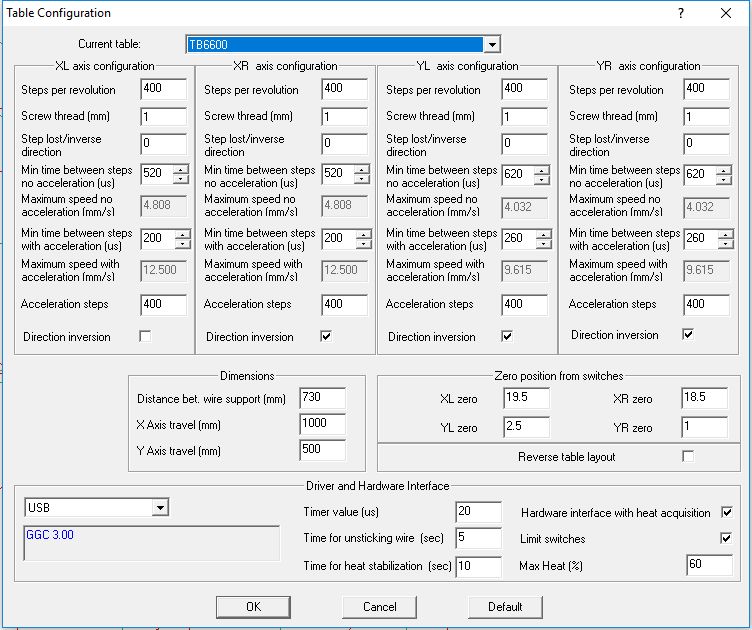
The motor is set to half step mode in the driver, so the number of steps per revolution is 2×200. To fully check the speed configuration, you have to performe two ways movements using the Zero axis dialog. The number of steps for performing acceleration is set to 400. The time between two steps for the no acceleration speed is 620us. With acceleration, it goes down to 260us.
These numbers are good. With my Letmathe motor interface, I get sightly better results with my openbuild table, but my power supply has also a higher voltage.