Step 1. Open the project “tuto_align.cnc”
Download the project from this url and save it to your PC in the directory of your choice.
Start GMFC PRO by double-clicking on the project. GMFC will open the project.
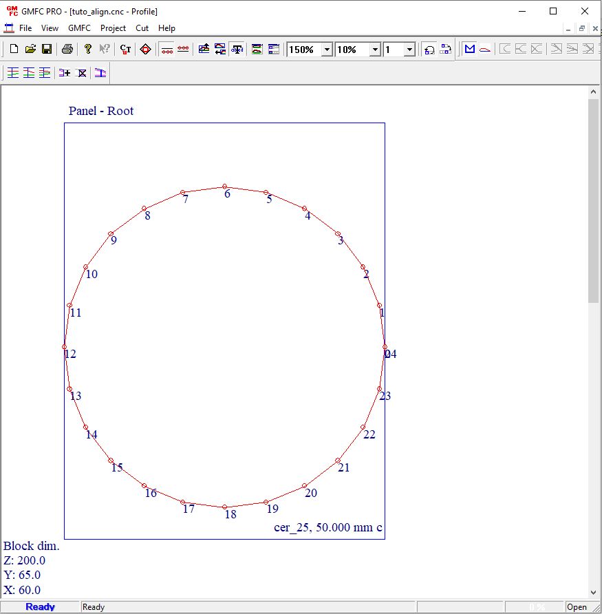
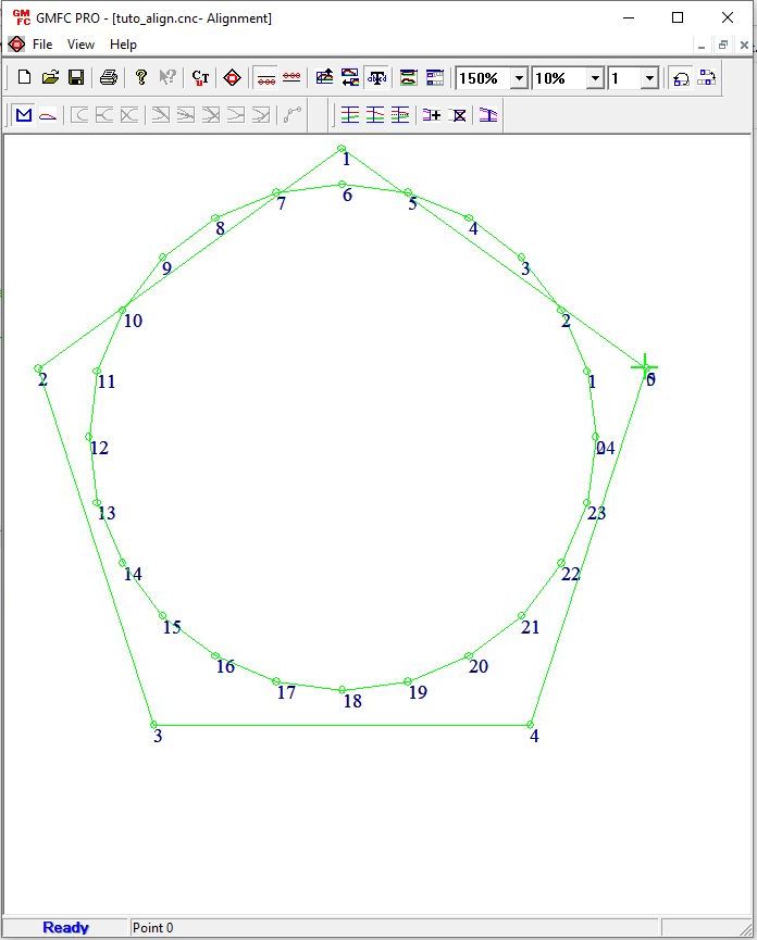
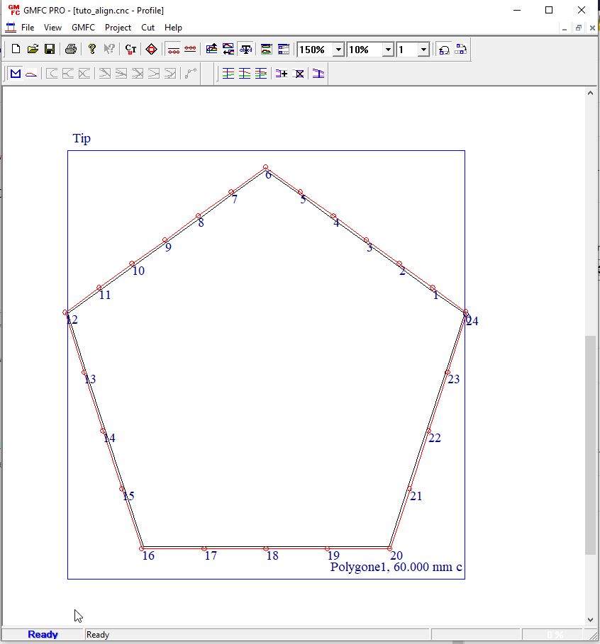
To show the points and their numbers, click on the “cut coordinate” icon, and set the point multiple to 1 in the toolbar.
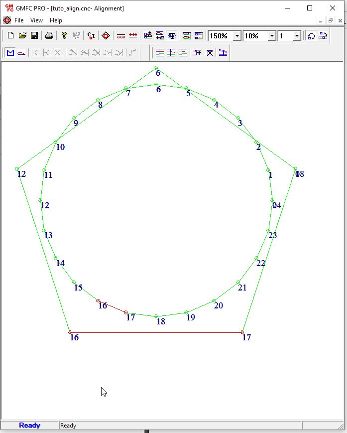
The project contains a circle of 24 points at the root side,
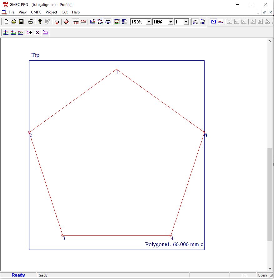
and a polygon of 5 points at the tip side.
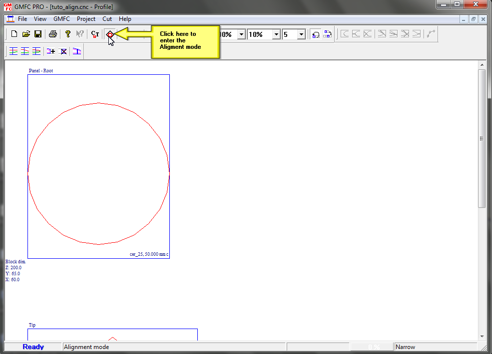
Step 2. Use the alignment mode
Click on the alignment icon in the toolbar.
The two shape are now displayed one on top of the other.
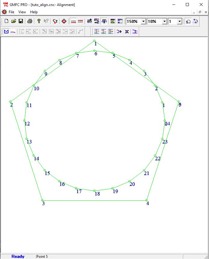
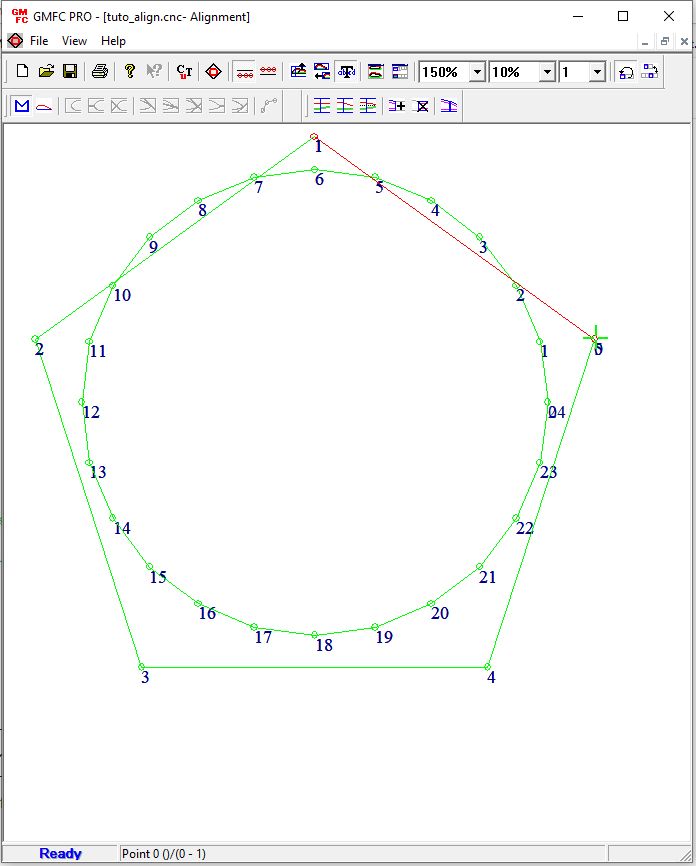
Now move the cursor on top of the point 0 of the tip. The cursor will turn into a green cross. If you move the cursor over a root point, the cursor turns to red. The number of the point is shown in the status bar.
While the cursor is on top of the tip 0 point, left click. The first segment of the tip is selected and is shown in red.
Now, move the cursor to the first point (point 0) of the root shape, and select the first segment by a left click.
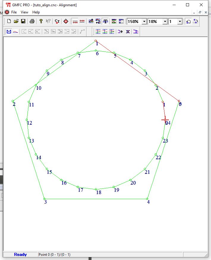
Then, move the cursor to the point 6 of the root and SHIFT+click on it. This will extend the selection from point 0 to point 6.
Note that the status bar shows the point under the cursor, and the current root/tip selections.
Now Right-click, the following menu will appear.
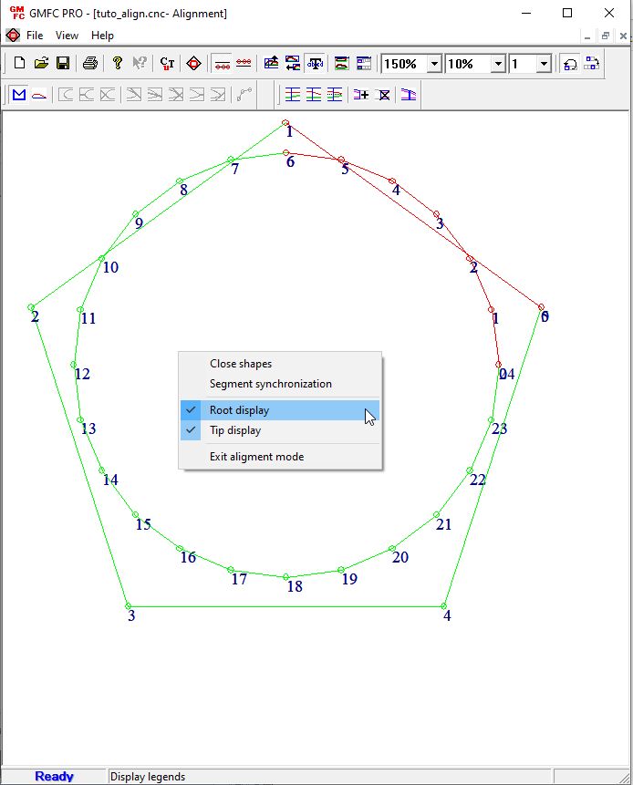
For information, the “Root display”/”Tip display” entry allows to enable/disable the display of root/tip shapes.
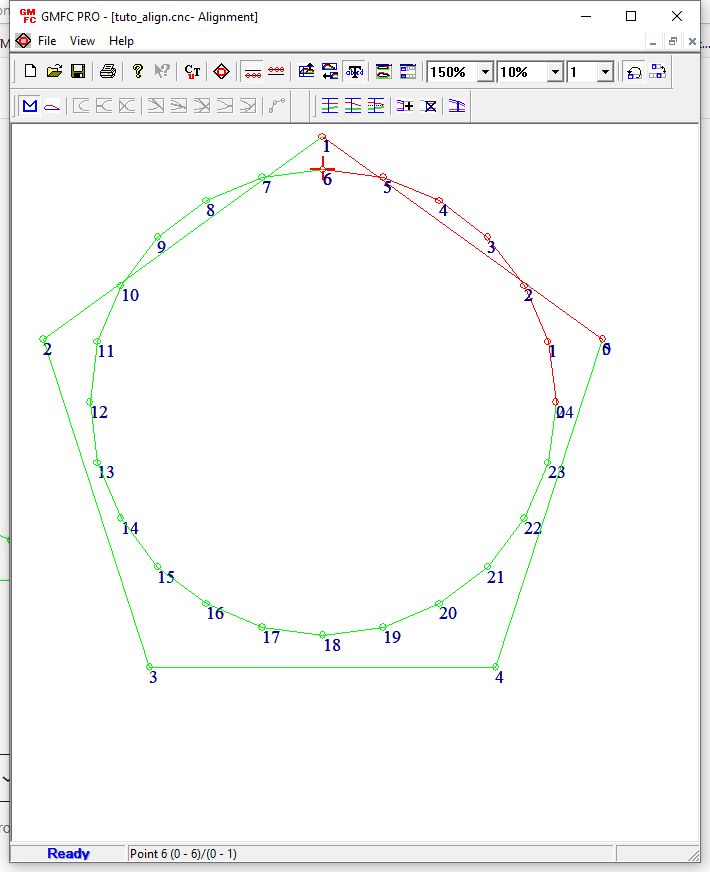
Click on “Segment synchronization”.
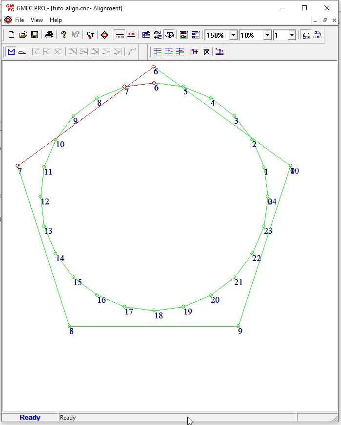
The first 6 segments are now synchronized. Note that the first point at the tip is numbered “6”. This means that the former first tip segment has been divided into 6 new segments.
Note that GMFC automatically selects the next segment at root and tip.
Now select root segments 6-12, by SHIFT+Click on root point 12.
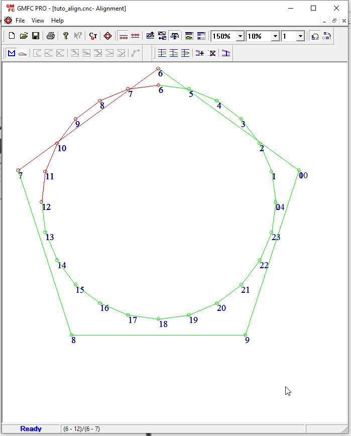
And synchronize these six segments again.
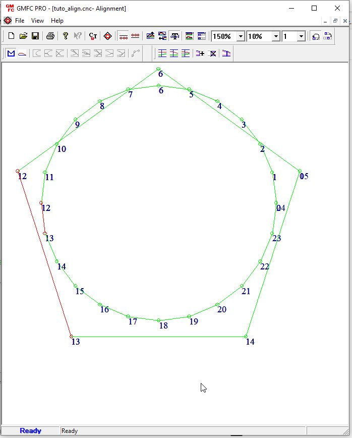
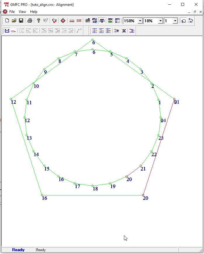
Repeat the process for root point 16.
Then do the synchronization with root point 20.
Finally for t the last tip segment, we use a different method. Put the cursor over tip point 20, and double click on it.
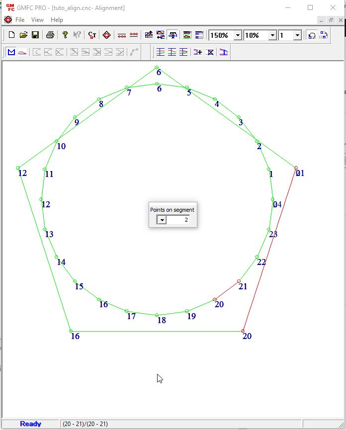
A dialog let you set the number of points in the segment. Change it from 2 to 5.
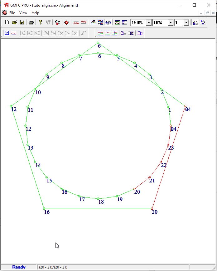
We have now the same number of points at root and tip. Synchronization is done. We can exit the alignment mode either by the entry in the menu, or the alignment icon.
So after exiting the alignment mode, we can see that GMFC has created the additional points in the tip shape.
So what we have learn? Click on a point sets the beginning of a selection. SHIFT+Click sets the end of the selection. “Segment synchronization” computes the smallest multiple number and adjust the number of points. Double Click allows to enter the number of points in a segment.
Step 3. Aligning the shapes
We want to center the shapes in X (and in Y). To do that, go to the panel management dialog.
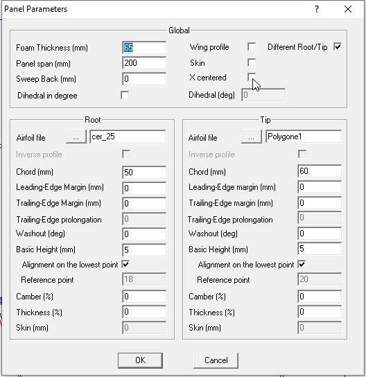
To center the two shapes in X, check the “X centered” box. GMFC will compute the sweep back when exiting the dialog. To position the shapes in Y, you have to adjust the “Basic height” values.
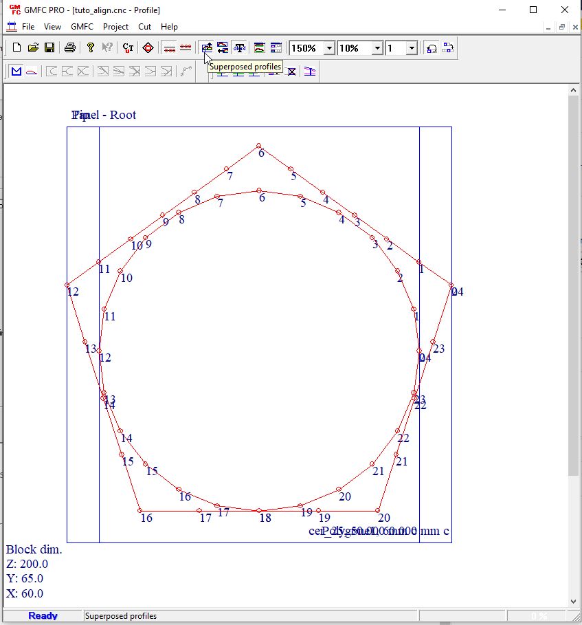
To check the shape positions, you can superpose the shape views using the “superposed profiles” icon in the toolbar.
Step 4. Cutting the project
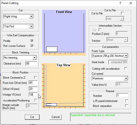
Go to the cutting dialog “Cut/Panel cut”. Set the foam type, and then the block position in Z.
For a precise cutting, I don’t place the block in the middle of the table, but at a specific offset from the root axis.
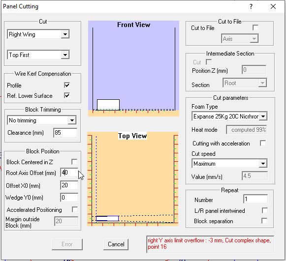
On my table, the closet position is 40mm from the root axis. As you can see in the picture above, GMFC tells that position does not work for this project, because at point 16 the wire would go underneath the table.
So we have to move the block. One solution is move it higher by using a foam wedge (or a higher block). Here a 10mm wedge will work.
The second solution is to move the block in Z further into the table. An offset of 240 will work.
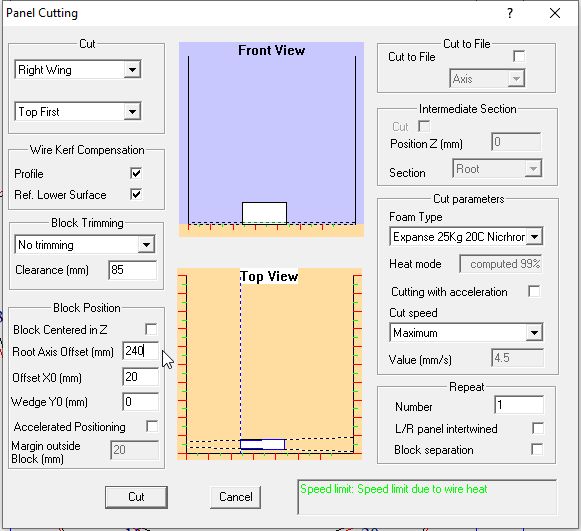
You can see that the error is gone. The information message turns to green which means that cutting will work. It also tells that the cutting speed (4.5 mm/s) is limited by the wire heat which in that case is 99%.
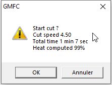
After pressing on the “Cut” button, you get this final dialog that summarize cutting parameters including the cutting time.
Et Voila… Your turn now.