This tutorial completes information that can be found in the help file that comes with GMFC. It is done for the EXPERT version that supports four different motors. If you use the PRO or LIGHT version, left and right motors have an identical configuration.
Table configuration
Open the Table Configuration dialog (GMFC/Table configuration).
The first thing to enter is the type of driver, parallel port or USB, that you use. If you use a GGC adapter, or the former MMUSB adapter, select the USB mode. Then, the timer value will be automatically determined.
If you use a parallel port based interface, select the appropriate entry with the corresponding timer value.
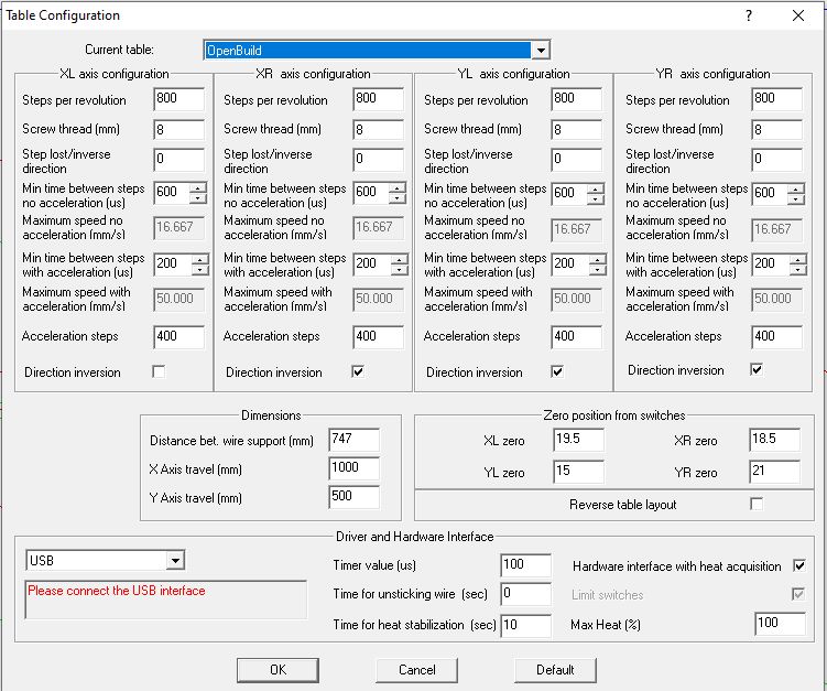
Then, you need to enter the characteristics of the motors, and the dimensions of your table:
Steps per revolution. That’s the number of steps required for the motor to perform one revolution. Older unipolar motors were 48, 50, or 100 physical (full) steps. Current bipolar motors are 100, 200, or 400 full steps. In addition to the physical steps, motor interfaces are able to insert intermediate (2, 4, 8, 16) steps between two full steps. The step configuration mode is set by the motor interface (usually using switches), and not within GMFC. Therefore, you must multiply the physical number of steps by the (inverse of the) step configuration mode. 1/2 and 1/4 step configurations usually provide smoother movements. In my openbuild table (see picture above), motors are 200 physical step motors used in 1/4 step mode. So steps per revolution equals 800.
Screw thread. That’s the distance the axis moves if the thread performs one revolution. If you are using a metric thread, you have to use the values in the following table:
| Type | Screw diameter | Screw thread |
| M6 | 6mm | 1mm |
| M8 | 8mm | 1.25mm |
| M10 | 10mm | 1.5mm |
| M12 | 12mm | 1.75mm |
In my openbuild table, I am using multi-threaded screws with an advance of 8mm per turn.
DIY or second hand screws are not always exactly at a metric thread value. To verify the exact screw thread, perform the longest possible displacement and measure the distance. The real screw thread equals:
Thread * (measured distance/entered distance).
Steps lost when going reverse. This is the number of steps that the motor does without moving the axis when changing direction. This value is not used by GMFC at the current time and should be set to 0.
Then, enter table dimensions:
Distance between wire supports. Be careful to measure the distance between the two wire support points, and not the distance between the Y axes.
Axes travel. That’s the maximum distance the axis can move. Be careful to measure the useful distance and not the length of screws.
Direction inversion. If the axis runs in the wrong direction, check this box to reverse movement. Therefore, you don’t have to modify cables.
Calibrating the table speed
Step motors have two behaviors in terms of speed: (i) From a complete stop, they can instantaneously reach a non-accelerated speed, (ii) then from the non-accelerated speed, they can increase speed progressively to a faster accelerated speed. The limit is given by the motor torque and the friction in the machine. Also, higher is the speed, lower is the motor torque. When the speed is too high, the motor torque becomes insufficient for moving the axis and the motor will stall. The calibration process is to determine the safe limit for the non-accelerated and the accelerated speeds. This is done by performing long distance travels for all axes using the GMFC/Zero axis dialog.
Precision is critical for foam cutting and safe fast movements. To achieve a high level of speed precision, GMFC relies on a high frequency timer, with a frequency of up to 50Khz (20 us) with the GGC adapter. For this reason, accelerated and non-accelerated speeds are specified in GMFC using the timer. Since speed = distance/time, time is expressed using a multiple of the timer value. Increasing the time lowers the speed, decreasing the time raises the speed.
There are three fields per axis to calibrate: (i)
- Minimum time between steps no acceleration, for the non-accelerated speed. Using the arrows will increase/decrease the time by one timer unit.
- Minimum time between steps with acceleration, for the accelerated speed. Note that acceleration is only supported by GMFC PRO and GMFC Expert.
- Acceleration steps. This is the number of steps that are used by GMFC to progressively reach the accelerated speed, from the non-accelerated speed. A number of steps corresponding to half a revolution is a good starting value.
Now, let’s open the GMFC/Zero axis dialog to perform the calibration.
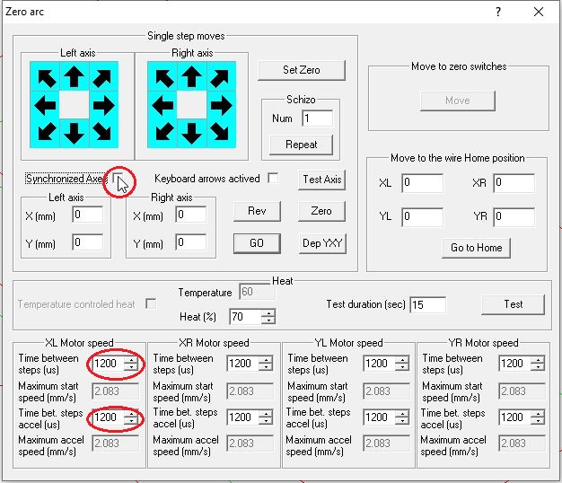
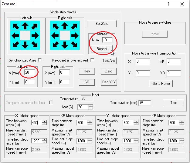
I have created a dummy table for the tutorial with 1mm screws and 200 steps motors used in half step mode that results to 400 steps in the table configuration. Set the Time between steps to a value (here 1200) so that the speed is around 2mm/s for all axes. This speed is sufficiently low to to work without problems. Be sure that acceleration is not used by having the Time between steps with acceleration equals or higher to the Time between steps. Uncheck Synchronized Axes, so that you can move all axes independently.
Let start with the Left X axis. Enter a distance between 10 and 50mm, and press Go to start movement.
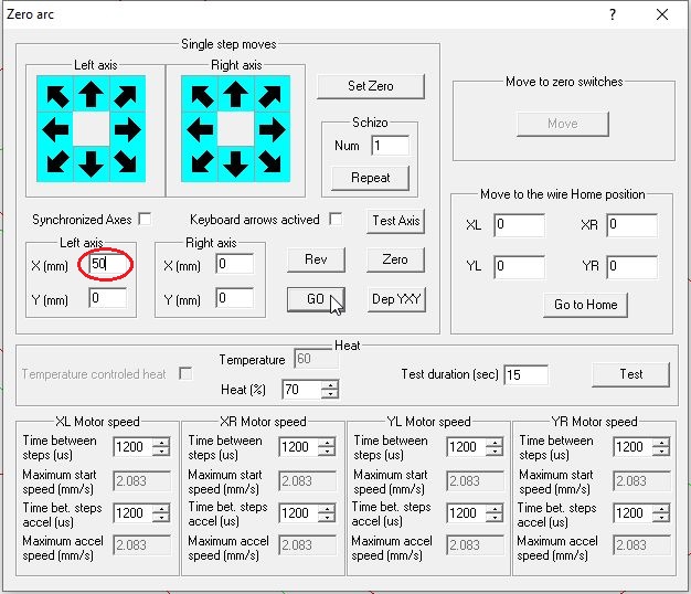
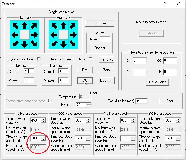
Check that the left axis has indeed made a move of 50mm. If not, check all table parameters.
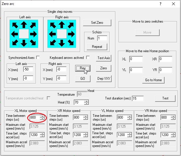
If the move is correct, you can now increase the speed to around 3mm/s, by lowering the Time between steps to 800us. You can inverse the direction of the movement by pressing on the Rev button that negates all distances. Please note that you should not use the arrows to test speed.
Repeat the process of increasing the speed until the motor stalls. We are now too fast.. and we need to lower the speed by one timer unit using the arrows (at the right of the Time field) until the motor travels safely without stalling.
Now, you must perform the “Schizo” test which is to chain up several round-trip travels. This ensures that when going reverse, the motor will not stall. Let’s do 10 round trips over a distance of 20mm.
The final test is to perform moves for the complete length of the axis, so that you are sure that there is no point of friction. Voila, the non-accelerated speed for the Left X axis is calibrated !
Let’s calibrate now the accelerated speed. The methodology is the same as the one for the non accelerated speed. Start by choosing a speed higher than the non-accelerated one, then test displacement.
Repeat the test while increasing the speed until you reach motor stall. Then, lower sightly the speed so as to be safe. Finally, you can adjust the number of acceleration steps in the table configuration so as to shorten or increase the acceleration phase. Note that with acceleration you may double the non-accelerated speed.
Now that we are done with the X left axis, you can check that the settings are also valid for the X right axis.
Finally, repeat the same process for the Y axes.