GMFC Expert allows to chose the number of cutting points within a DXF object such as an arc or a spline. This is useful for synchronizing two different profile. Here is an example for a turtle deck like project. We will use two dxf files turtle_root and turtle_tip. Save them into a local directory before starting this tutorial.
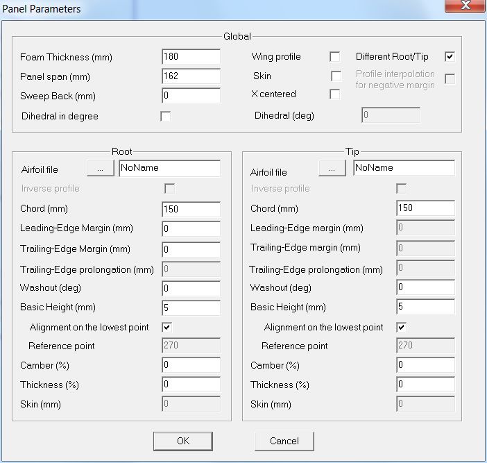
Let’s start … Run GMFC Expert which creates a new project at startup. Double-click on the background that is a short-cut to the panel dialog and set the « Different Root/Tip » box. Exit the panel dialog.
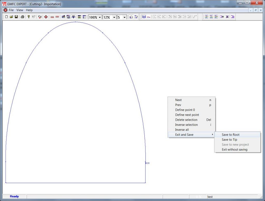
Then, click on the « File/ Dxf-Hpgl Import » menu. A file explorer window appears. Navigate to the directory in which you saved the dxf files and chose « turtle_root.dxf ». The profile is now displayed with a circle at the end of each dxf object. Right-click on the background, then chose « Exit and save/Save to root ».
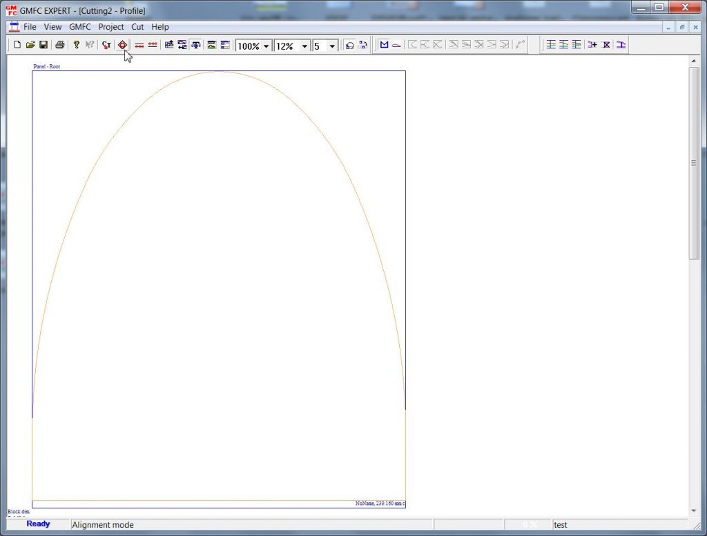
Import now the « turtle_tip.dxf » in the same way as for the root. Just chose « Exit and save/Save to the tip ».
Go to the alignment mode. There is a shortcut in the tool bar, click in the red circle inside the black box under the cursor as shown in the picture below.
Now both profiles are displayed on top of each other. First, it is convenient to set point numbering to 1 so as to show the number of points in each dxf object.
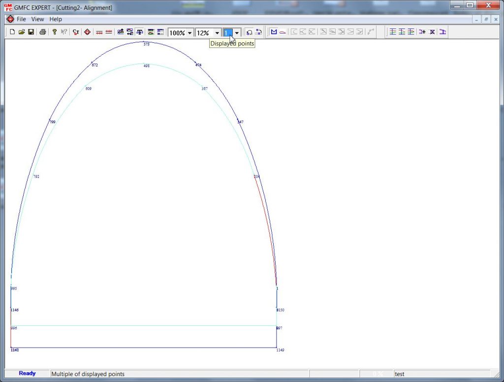
Note that you may chose to not display one of the profiles. This is sometimes useful when the profiles are intertwined. Right-click on the background, then unselect the undesired profile.
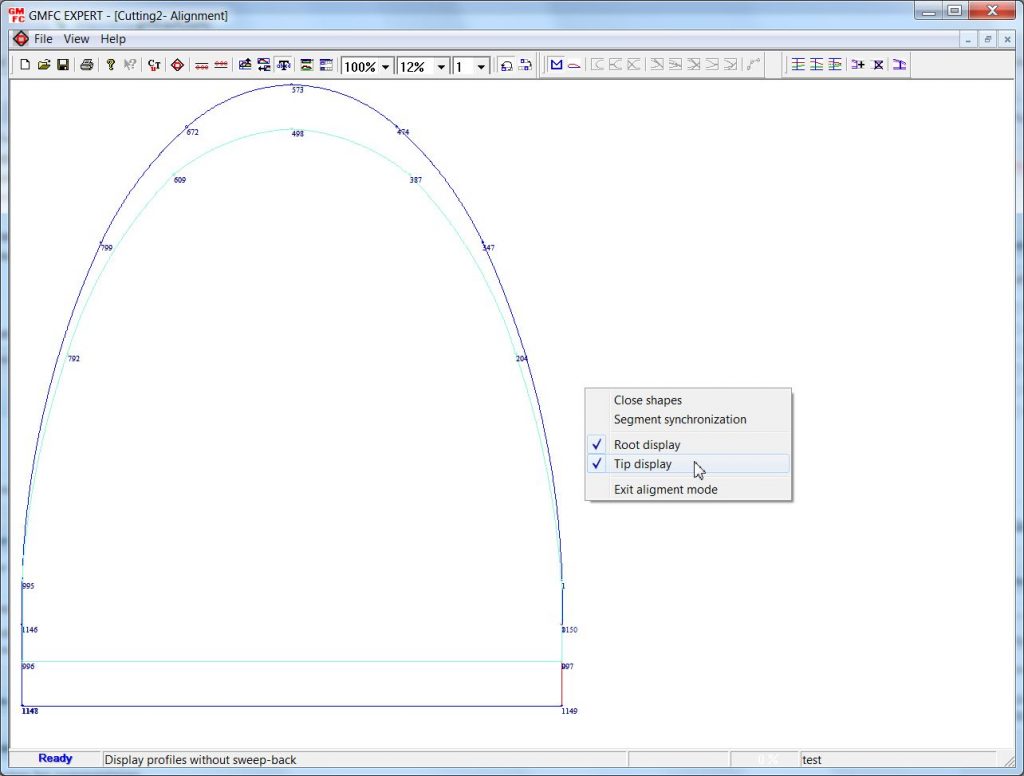
Let’s just display the root for now since we need to change the entry point, i.e., the point 0. Move the cursor to point 1148 which is on the bottom-right of the profile. When the cursor is on a point, it switches to a red cross.
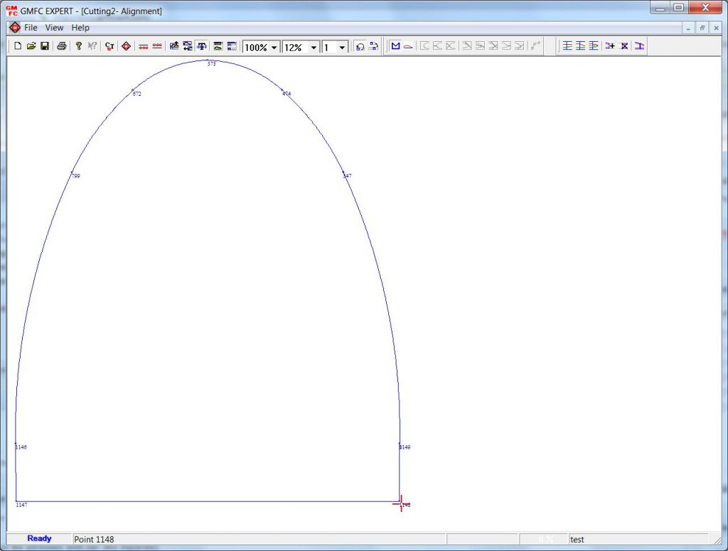
Click-right and select « Define 0 point here ». That’s it…
Now let’s do the synchronization job. Remember that the goal is to decide where the wire should be on each side of shape at a given time. So, we need to assign a number of points to each dxf object and we will do this for each profile. In this example, both profiles are similar ; they contain the same number of dxf objects and they only differ in size. The task is easy ; every dxf object on each side will be given the same number of points.
The first dxf object is a straight line, it contains 2 points. No need to change that. The second object is an arc. To change the number of points, move the cursor to the object start circle and double-left click. A window with the current number of points in the object appears.
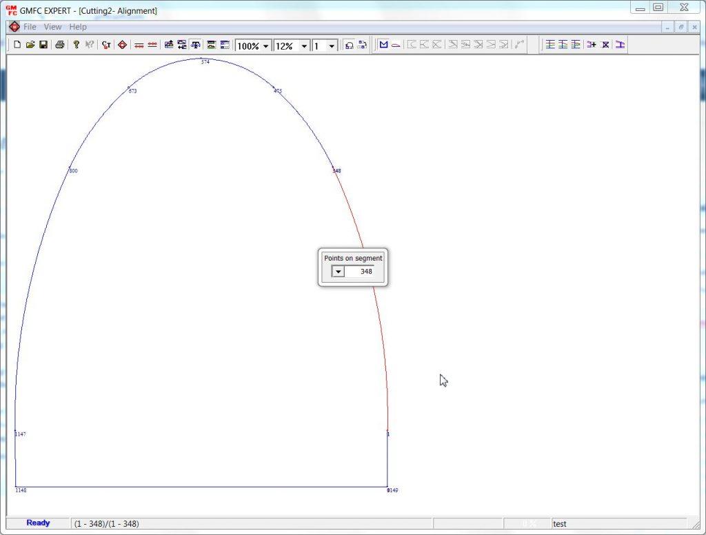
The current values is 348. Let’s change this to 100. Now repeat the process for each dxf object. Adjust the number of points to the desired cutting precision. Here is the result for the root using 30 points for the smaller dxf objects.
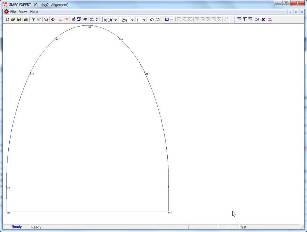
Now switch to the tip side and repeat the point setting process. Exit the synchronization menu and you are done !!!
Final tip: If the two profiles do not contain the same number of dxf objects, you have to decide of where are the synchronization points. Therefore, an object on one side may correspond to several objects on the other side. Adjust the number of points accordingly.